礼貌灯电路--Courtesy Light
15 seconds delayed switch-off
A good idea for bedroom lamps

Parts:
R1____________470R 1/2W Resistor
R2____________100K 1/4W Resistor
R3______________1M5 1/4W Resistor
R4______________1K 1/4W Resistor
C1____________330nF 400V Polyester Capacitor
C2____________100΅F 25V Electrolytic Capacitor
C3,C5__________10nF 63V Polyester or Ceramic Capacitors
C4_____________10΅F 25V Electrolytic Capacitor
D1,D2________1N4007 1000V 1A Diodes
D3_________BZX79C10 10V 500mW Zener Diode
D4__________TIC206M 600V 4A TRIAC
Q1____________BC557 45V 100mA PNP Transistor
IC1____________7555 or TS555CN CMos Timer IC
SW1____________SPST Mains suited Switch
Device purpose:
This circuit is intended to let the user turn off a lamp by means of a switch placed far from bed, allowing him enough time to lie down before the lamp really switches off.
Obviously, users will be able to find different applications for this circuit in order to suit their needs.
Circuit operation:
Due to the low current drawing, the circuit can be supplied from 220Vac mains without a transformer. Supply voltage is reduced to 10Vdc by means of C1 reactance, a two diode rectifier cell D1 & D2 and Zener diode D3. IC1 is a CMos 555 timer wired as a monostable, providing 15 seconds on-time set by R3 & C4. When SW1 is closed, IC1 output (pin 3) is permanently on, driving Triac D4 which in turn feeds the lamp. Opening SW1 operates the monostable and, after 15 seconds, pin 3 of IC1 goes low switching off the lamp.
Notes:
The circuit is wired permanently to the mains supply but current drain is negligible.
Due to transformerless design there is no heat generation.
The delay time can be varied changing R3 and/or C4 values.
Taking C4=10΅F, R3 increases timing with approx. 100K per second ratio. I.e. R3=1M Time=10 seconds, R3=1M8 Time=18 seconds.
Low Gate-current Triacs are recommended.
Use a well insulated mains-type switch for SW1.
Warning! The circuit is connected to 220Vac mains, then some parts in the circuit board are subjected to lethal potential!. Avoid touching the circuit when plugged and enclose it in a plastic box.
This circuit was awarded with publication in ELECTRONICS WORLD "Circuit Ideas", April 2001 issue, page 299.
相关热词:#灯电路
 无线遥控器电路图制作
时间:2026-03-07
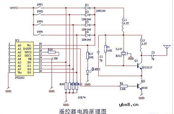 无线电遥控门铃电路原理图
时间:2026-03-07
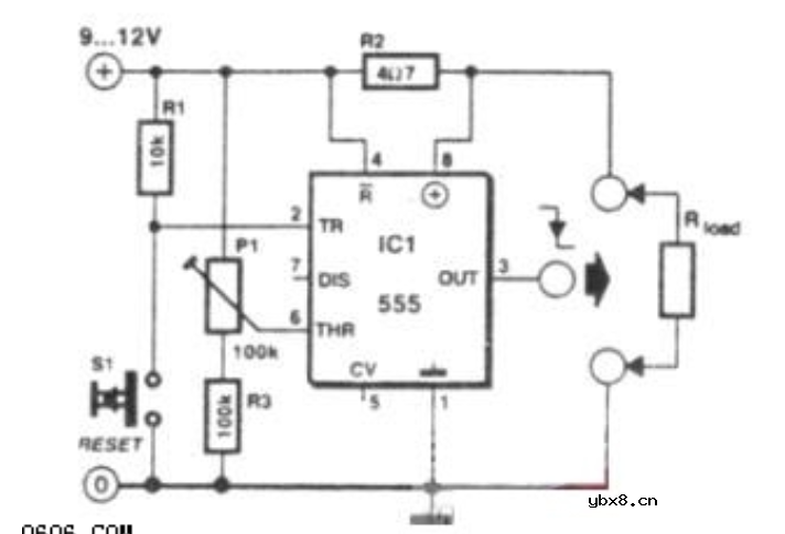 NE555过流保护检测器电路图
时间:2026-03-07
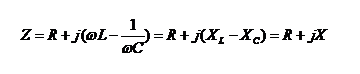 串联谐振升压原理
时间:2026-03-07
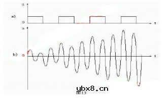 谐振回路的工作原理
时间:2026-03-07
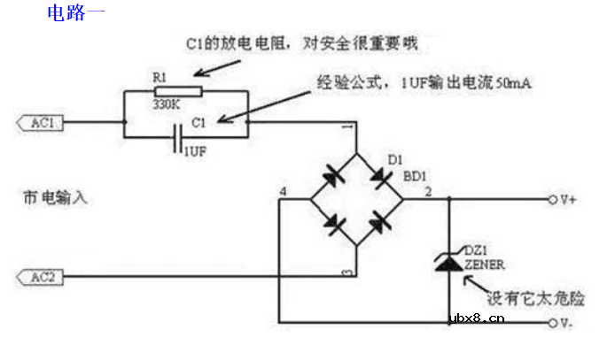
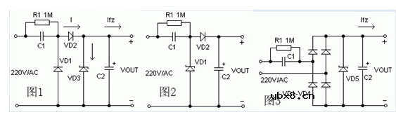 电容降压电路原理
时间:2026-03-07
 实用的电容降压电路
时间:2026-03-07
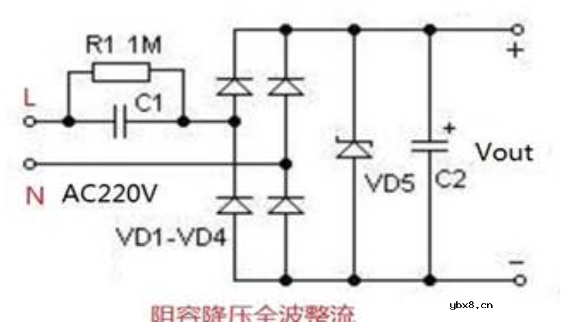
 低成本的阻容降压电路原理图分析
时间:2026-03-07
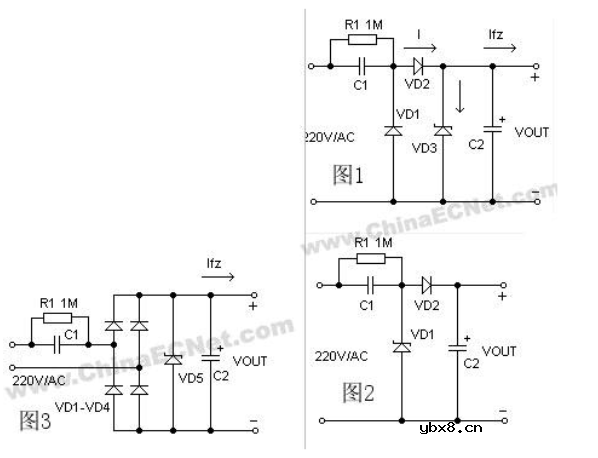 阻容降压原理及电路
时间:2026-03-07
 阻容降压电路的误区
时间:2026-03-07
 彩灯电路
彩灯电路
时间:2026-03-05
三相异步电动机原理
时间:2026-03-04
三相异步电动机的七种调速方式
时间:2026-03-04
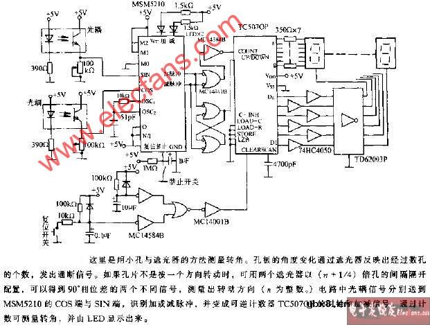 转角测量电路
时间:2026-03-05
 经典的正弦波发生电路
时间:2026-03-05
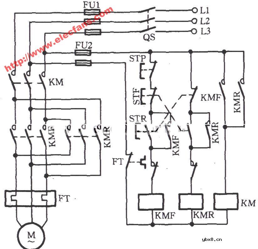 电动机单线远程正反转控制电路图
时间:2026-03-04
三相异步电动机的拆装详讲
时间:2026-03-04
 USB转232电路图
时间:2026-03-04
电度表的工作原理
时间:2026-03-04
 电风扇红外遥控器2
时间:2026-03-04