单极性步进电机控制器电路--Unipolar Stepper Motor Controller
This is a very good integrated circuit. There is no need for any external glue logic to drive the circuit, there is only 2 pins to drive the motor, one for controlling the direction and the other to trigger the stepping pulses. It provides a very compact design that drives 5 or 6 or 8 wire stepper motors. The 5 or 8 wire stepper motors are treated as a variation on the 6 wire motor. That is, the 5 has the two common wires from the coils center taps joined inside the motor (saves joining them outside the motor), however some confusion may occur with the ends of the other coils as to which joins with which, however trial and error to determine this will not hurt anything. In the 8 wire motor case the joined center taps will have to worked out by you. You will know which coil is joined to which coil, however experimentation may be required to determine polarity.

The resistors R1 & R2 are only necessary if the supply voltage to the motors is above 10 volts or so, and are really only necessary near max voltages and tuning the response times of the motor for high speeds. See data sheets for details.
There should be very little problem getting hold of six wire motors that make the connections obvious. These motors are by far the most common where any degree of power is required, e.g. in printers. Non-working dot matrix printers are fairly common now-a-days and the motors in them are excellent starting points for experimentation. You will also get belts, pulleys and gears thrown in (may be even a power supply if your are adventurous).
A very simple Printed Circuit Board Design

Features of the chip:
1.5A Maximum Output Current
35 V Output Sustaining voltage
Wave-Drive, Two-Phase, and Half Step Formats
Internal Clamp Diodes
Output enable control
Power on reset
Internal Thermal Shutdown
Sequence Connections
Two-Phase Drive Sequence Pin 9 GND Pin 10 GND (Simplest choice)
Wave Drive Sequence Pin 9 5v Pin 10 GND
Half Step Drive Sequence Pin 9 GND Pin 10 5V
This driver will allow you to scale up your project considerably as the power will be much greater with the bigger motors and higher voltages and currents. The draw back is that the engineering that goes along with them will also have to be more substantial. The larger stepper motors are very heavy for desktop models but will be very versatile for the larger experiment.
Commercial Kit and Data Sheets
An excellent, high quality kit (Nos:109) to experiment with this driver can be purchased from
Wiltronics Research PTY LTD
5-7 Ripon St (North)
Ballarat 3350
AUSTRALIA
Phone (03)5331 1947
It provides a 5 volt regulated supply, indicator LEDs, 555 oscillator for pulses and miniature switches to control direction and stepping modes. Single step or free funning can be chosen as well full data sheets provided. They also provide data sheets with the circuit. Contact them for prices. While not the cheapest way to go it is the best seen so far.
[责任编辑:电子发烧友---转载请标明出处]
相关热词:#步进电机
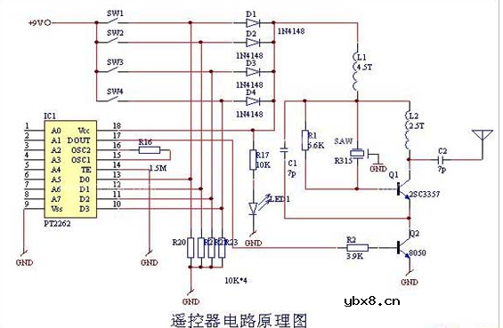
 无线遥控器电路图制作
时间:2026-03-07
 无线电遥控门铃电路原理图
时间:2026-03-07
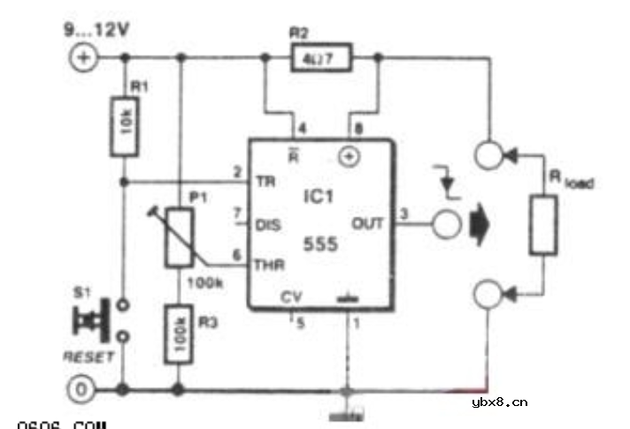 NE555过流保护检测器电路图
时间:2026-03-07
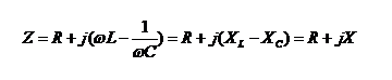 串联谐振升压原理
时间:2026-03-07
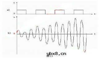 谐振回路的工作原理
时间:2026-03-07
 电容降压电路原理
时间:2026-03-07
 实用的电容降压电路
时间:2026-03-07
 低成本的阻容降压电路原理图分析
时间:2026-03-07
 阻容降压原理及电路
时间:2026-03-07
 阻容降压电路的误区
时间:2026-03-07
 彩灯电路
彩灯电路
时间:2026-03-05
三相异步电动机原理
时间:2026-03-04
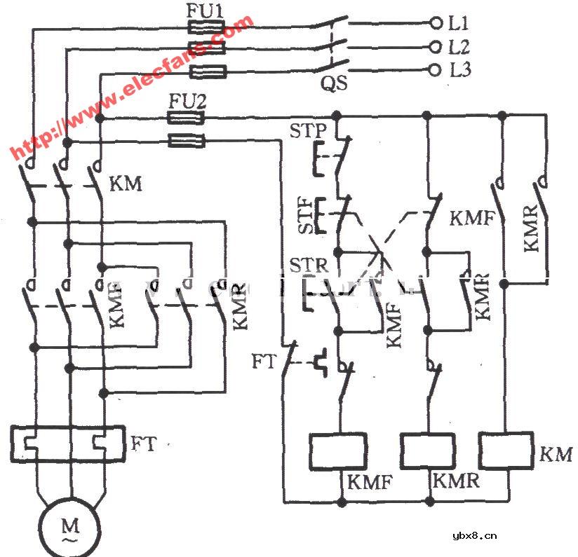 电动机单线远程正反转控制电路图
时间:2026-03-04
三相异步电动机的七种调速方式
时间:2026-03-04
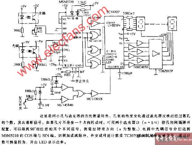 转角测量电路
时间:2026-03-05
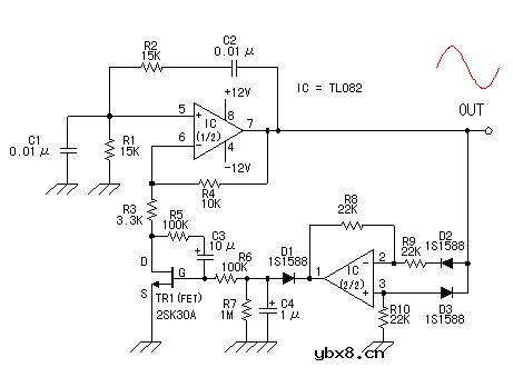 经典的正弦波发生电路
时间:2026-03-05
三相异步电动机的拆装详讲
时间:2026-03-04
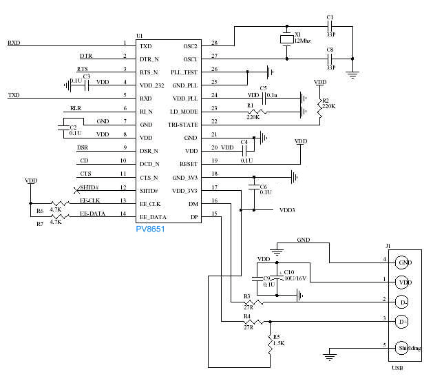 USB转232电路图
时间:2026-03-04
电度表的工作原理
时间:2026-03-04
 电风扇红外遥控器2
时间:2026-03-04